The Standard
|
The Schedule
|
Overview
For this standard you need to demonstrate the development of each of the subsystems and finally the interfacing of the subsystems into one functional model.
The inputs in the diagram can be considered sensors and the outputs as actuators for this standard.
You should document the development of each subsystem as follows:
Achieved:
Excellence: Evidence of substantial improvement (Using a LCD screen as an example):
The inputs in the diagram can be considered sensors and the outputs as actuators for this standard.
You should document the development of each subsystem as follows:
Achieved:
- Why you use it/what it does - a paragraph
- How you wire it up - a schematic or breadboard diagram
- Code you wrote to get it going - insert file attachment or copy and paste in your code
- Evidence that it works - insert photos or videos
- analogRead a value from a potentiometer and display it on an LCD screen - insert file attachment or copy and paste in your code
- What faults did you get? - insert photos or videos
- How did you solve the faults? - insert file attachment or copy and paste in your code & insert photos or videos of it working as planned
Excellence: Evidence of substantial improvement (Using a LCD screen as an example):
- Use an IC to decrease the number of digital pins used - schematic, code, photo/video evidence and justification of improved operation
RGB LEDWe are going to use RGB LED's to help sense the colour of objects and display the colour of sensed objects to the user.
Here is a datasheet for the RGB LED's that we will be using. Have a read of this tutorial and use the information it contains to select current limiting resistors for the LEDs. Solving servo glitchYou may have observed that Servos may not move smoothly, are glitchy or twitchy when they are controlled by an Arduino. The reasons for this are a little complicated and are to do with how the Servo library was written. Here are some possible solutions:
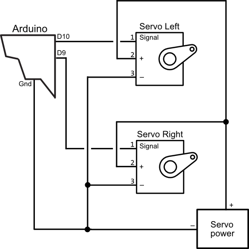
User ControllerYou are developing this in your prototyping standard. You need to include:
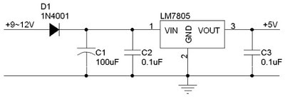
This schematic shows you how to wire up a voltage regulator. D1 protects the circuit if the wall wort gets connected backwards. C1 smooths the input voltage to remove any remaining AC ripples. C2 and C3 filter any remaining 50Hz variation from the input and output respectively.
IR CommunicationWouldn't it be good to have a wireless controller? Maybe you could an an IR transmitter and battery to your controller and an IR receiver on your servo driver...
|
LCD ScreenLCD screen are very useful for giving the user information without them needing to connect their Arduino to a computer and use the serial monitor. You can use them to help display user interface menus, the mode that a project is in or the value of variables. They can also be very helpful when it comes to fault finding a project.
Here is an instructable that explains how to connect an Arduino to an LCD display and below is the wiring diagram. 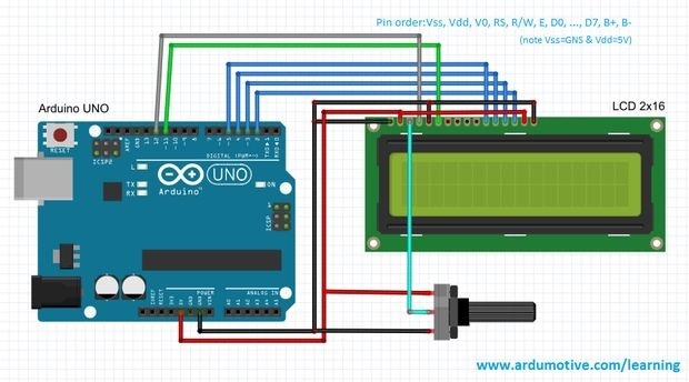
After wiring it up as shown you should be able to start the Arduino IDE and open files-examples-Liquid Crystal-Hello World, upload it and see text displayed on the screen. You may need to turn the contrast pot a little.
You will notice that connecting an LCD screen requires 6 digital pins if you are aiming for merit or excellence you might consider using an LCD driver circuit to decrease the number of Arduino pins required. 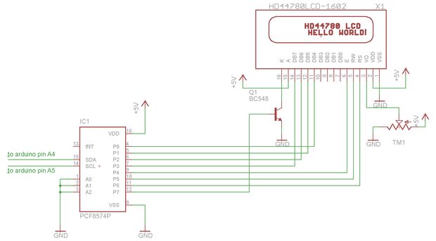
Servo Noise (optional)Long wires can pick up electrical noise as they tend to act as antenna for electromagnetic interference generated by nearby electrical components. A common source of noise is electric motors, like those in servos.
So it can be a good idea to clean up a signal going to a servo so that it functions as intended. This website explains how and why 'servo noise traps' are used. Here is the schematic they suggest to use. The 4069 IC is an inverting buffer. It amplifies the input signal which has the effect of clipping any noise out of the signal. 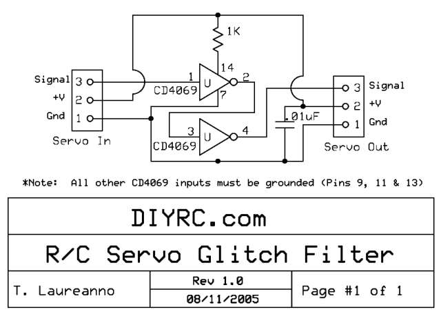
5V RegulatorTo make your project more portable we are going to run it off a wall wart transformer. The transformers can provide more current to our circuits than a USB port, which is good for driving motors/servos reliably.
The Arduino we are using needs 5V, any more and it will get damaged. To step the higher voltage from the wall wart (9-12V) down to 5V we need a voltage regulator. Check out the datasheet for our voltage regulators here and this video explaining how they work: |