The Standard

|
Student Task
|
Evidence Template
|
Line Sensor Circuit
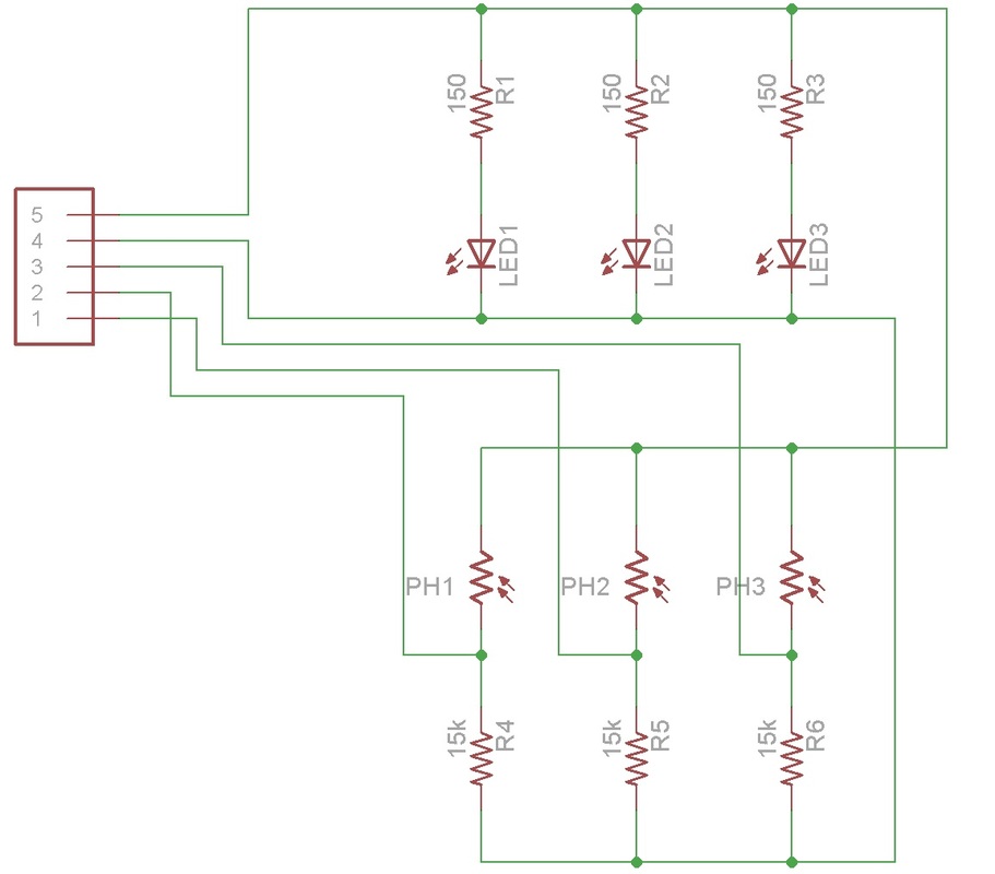
This is a possible circuit you could use for your line sensor. You really only need to light sensors; one on the left and one on the right. That way you can aim to keep the line between the two sensors.
Note: the resistor symbols used are the zig-zag lines, these are the American symbols for resistors. The top set of resistors are the current limiting resistors for the LEDs and the bottom set make potential dividers with the LDRs. |
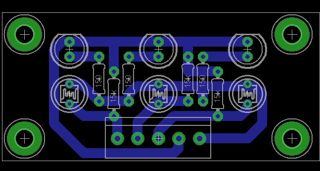
This image shows how the components could be laid out on a line sensing PCB when looking from above (not the copper side). Note the direction of the LEDs and the values of the resistors.
|
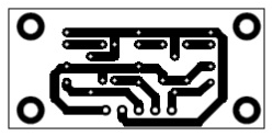
The copper tracking as seen from below (the copper tracking side). If you are printing this out do not scale the image as it has the same pin spacing as your components.
Use this as a template for drilling holes for your component leads, hand drawing your tracking before etching and checking for short circuits with a multimeter. |
H-Bridge IC

|
To the left is a link to the datasheet for the L293D integrated circuit that we are using to breadboard our robot motor drivers.
|
Breadboard Testing
|
How to power your motor driver breadboard using your Arduino and a 3xAA battery pack.
|
How to check you have wired your chip correctly by measuring the voltage on the chip pins.
|
How to check your chip is switching on and off correctly.
|
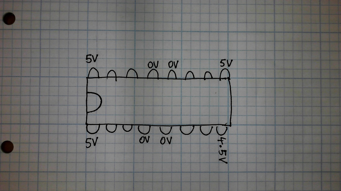
This first image shows what voltages you some measure on certain pins of your motor driver chip if it is wired correctly
|
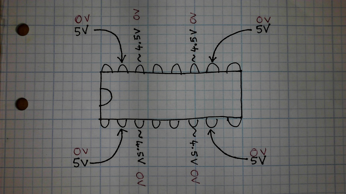
To test the driver chip is switching correctly connect 0V or 5V to the pins indicated with an arrow and you show measure the corresponding values on the pins next to them
|
Robot Test Code

|
Download this .ino file. It contains code that can be uploaded to your Arduino board and used to test if the connections on your robot are working correctly. You may need to open the Arduino programing environment first and then open this file.
Before uploading check that "Tools-Board" is "Arduino UNO" and "Tools-Serial Port" is set correctly. You need to make the following connections between your Arduino and breadboard:
|

