The Standard
|
Student Task |
Mark Scheme |

|

This document explains what you need to submit and how to submit it
|

This document is what I will be using to mark your work. Make sure you submit all of the evidence required for the grade you are aiming for
|
Standard Overview
This standard is closely related to AS91079, Constructing an Embedded System. This standard has a stronger focus on the physical construction of an electrical circuit and interfacing that circuit with the code on your microcontroller.
Selecting Current Limiting ResistorsHave a read of this tutorial and use the information it contains to select current limiting resistors for the LEDs on your line following circuit.
Aiming for excellence? Use this LED datasheet to provide evidence for the data used in your calculations when selecting your current limiting resistors. 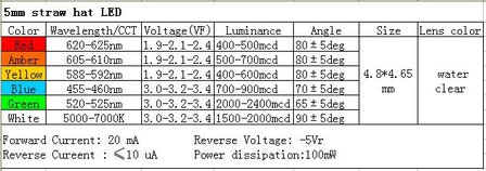
|
Selecting Fixed Resistors for your LDR Potential DividersHave a read of this tutorial (scroll down to the section on 'Choosing a Resistance Value') and use the formula to select suitable values for the resistors you will put in your LDR potential dividers.
|
Line Following Circuit
You need to create a circuit diagram that you are going to use to fabricate your line sensing PCB. So what does your circuit need?
So you need to draw a circuit that you could use that contains two sections above and a header pin for connect it to your Arduino. If you are making more than one PCB each PCB will need its own header.
When you have drawn out your circuit get your teacher to check it and you can start constructing it in Eagle.
- Light sensors (LDR potential dividers, at least 2 at most 6)
- LED's to illuminate the surface
So you need to draw a circuit that you could use that contains two sections above and a header pin for connect it to your Arduino. If you are making more than one PCB each PCB will need its own header.
When you have drawn out your circuit get your teacher to check it and you can start constructing it in Eagle.
Constructing a Schematic in Eagle
Check out the How To page on Eagle if you need some tips on creating schematics and laying out PCB in Eagle.
Creating a PCB
|
|
This video covers most of the techniques that we will use but with a few differences. We will transfer the the printed PCB layout onto a yellow transfer film before using the laminator to put it onto the copper PCB.
We use rotary tool drill presses for for drilling the holes in the PCB. It is important to hold your work down firmly when using these and make sure the bit is fully retracted before moving the PCB. If you do break a bit please let me know so I can give you another one and order some more. Cheers. |
|
|
So I haven't tried this yet but it looks like a more reliable method for transferring toner. I think a laser printer is required. You can check out the instructable here.
|

